


Posted to News on 26th May 2020, 00:00
Dual AMR motor position sensor for safety critical tasks
Enda Nicholl, strategic marketing manager at Analog Devices, looks at the trends in in automotive electrification as we move toward partial and full autonomous driving and, in particular, the changes required to make electrical power steering (EPS) and electrical braking systems meet the necessary safety standards to ensure the safe and reliable control of driverless vehicles.
The increased emphasis to improve vehicle safety in recent years has resulted in the welcome advancement and introduction of active advanced driver assistance systems (ADASs) to complement the traditional passive systems reliant on airbag deployment for driver and passenger safety. These emerging systems are intended to initially aid—but longer term replace—the driver’s vehicle manoeuvre decision making in safety critical situations.
These technology advancements are also leading the way to the transition to semi- and fully autonomous driving. Replacing the driver’s decision making with electronic control units (ECUs) and replacing the steering and brake manoeuvring of the vehicle with actuators is shifting responsibility away from the driver to the sensors, the ECUs, and the electrical actuators.
This trend is leading to the development of more reliable, intelligent, higher performance, and redundant electrical actuator solutions that need to comply with the ISO 26262 functional safety standard. This is a risk-based safety standard, where the risk of hazardous operational situations is qualitatively assessed, and safety measures are designed into the components and system to avoid or control systematic failures and to detect or control random hardware failures or mitigate their effects. These actuator systems generally use brushless dc (BLDC) motor drives, and as these systems are safety critical, the designers must design the solution hardware and software such that the system complies with the highest automotive safety integrity level (ASIL) D.
BLDC motor commutation
Brushless dc motors, as the name suggests, have no brush contacts, and motor position sensors (MPSs) are needed to measure the relative position between the stator and rotor to ensure the correct stator coil energizing sequence. This is particularly critical at startup when there is no back EMF available and it is impossible for the microcontroller to determine the relative rotor and stator positions. Traditionally, block commutation, which is comprised of three Hall switches, has been used to indicate the rotor position in BLDC motors. The demands to improve performance and, in particular, reduce noise, vibration, and harshness (NVH) and improve running efficiency of BLDC motor drives (including EPS systems) is resulting in a move away from block commutation to sine commutation control.
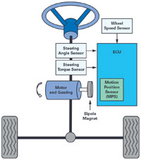
The Hall switches can be replaced with an MR angle sensor positioned in front of a bipole magnet mounted onto the end of the motor shaft. It is also typical for the MPS to be mounted onto the ECU assembly and for the ECU to be integrated into the motor casing and positioned at the end of the motor shaft.
Functional safety
ISO 26262 was introduced in 2011 as a safety standard to address the possible hazards caused by electrical safety-related system failures and has subsequently been replaced with a 2018 edition.
A safety and risk analysis must be carried out on the system to determine the ASIL of the system. The ASIL rating is established by reviewing the system’s potential hazards during operation in terms of severity, exposure, and controllability.
For example, if we do a risk and hazard analysis on an EPS system, it will be concluded that severe events such as steering blocking and self-steering land in the ASIL D category because of the severity, controllability, and exposure of these events. Similarly, for upcoming electrical braking systems, the same logic applies to the severity of uncontrollable events such as brake blocking or self-braking. Following on with the EPS or braking system examples, the ASIL D system rating can be achieved through subsystem decomposition.
It is not required that each system component be developed to ASIL D standards and processes to enable ASIL D system compliance; however, the overall system must fulfil the requirements when viewed at system level and can incorporate QM, ASIL A, B, C, or D level subcomponents as part of the system.
The system decomposition should also ensure a sufficient independence and take into account the possibility of dependent or common cause failures.
EPS system topology
A typical EPS system topology is as outlined in the diagram. The EPS ECU calculates the assisting power needed based on the steering torque being applied to the steering wheel by the driver, the steering wheel position, and the vehicle’s speed. The EPS motor rotates a steering gear with an applied force that reduces the torque required from the driver to manoeuver the steering wheel.
The motor shaft position (MSP) angle combined with phase current measurement information is used for the commutation and control of the EPS motor drive. The torque assistance level required varies depending on the driving conditions and is determined by the wheel speed sensors and the torque sensor, which measures the torque applied to the steering wheel by the driver or by the motor actuator in driverless cars. The microcontroller then uses the MSP data in combination with the phase current data to control the current loads supplied to the motor that provide the needed assistance.
Position and phase current sensors
An MPS sensor fault or failure could potentially cause or contribute to a severe system failure such as steering lock or self-steering, and for that reason the MPS is a critical component in the EPS system. It is therefore essential that the system has comprehensive diagnostic coverage of sensor faults and redundancy built in to ensure continued functionality in the event of an MPS sensor error or fault and ensure severe system failures cannot occur, or in the event an error does occur, that the system fails in a safe manner.
Current sense amplifiers are typically used for the indirect precision measurement of the motor load and normally applied to two of the three motor phases, thus enabling additional diagnostic information that can be used as part of the overall system safety case.
In addition, high precision motor position and phase current measurements allow for improvements in the EPS motor control performance that—at a system level—result in a very efficient, quiet, and smooth steering feel, improving the overall driver experience, and are therefore critical components in the system.
Functional safety in EPS motor control
Different approaches can be taken to achieve an ASIL D compliance in an EPS or other safety critical motor control application. The following example explains a dual anisotropic magnetoresistive (AMR) motor position sensor combined with the current sense amplifiers from ADI could be integrated into such a system and provide the required level of performance and redundancy needed to achieve ISO 26262 ASIL D compliance at a system level.
The dual AMR sensor can be complemented with an additional sensor based on an alternate technology (for example, Hall, GMR, or TMR). The dual AMR sensor is used as the primary (high precision) sensing channel, and the secondary alternate sensor technology channel serves three purposes:
- Enable the provision of a 2-out-of-3 (2oo3) comparison to validate if there is a fault with one of the sensor channels when combined with other system inputs.
- Provide position feedback in the unlikely event that both AMR channels fail.
- Provide the 360 quadrant information to the microcontroller needed for motor commutation in the event the motor has an uneven number of poles.
The precision angle measurement will continue to be provided by both channels of the dual AMR sensor. Additional system diagnostics such as motor load and shaft position can be indirectly inferred in a dynamic state (back EMF) from the precise phase current sense amplifier.
If we look at all the possible sensor failure modes in this sensor architecture example, there should always be two position sensor inputs available for a plausibility check. Even in the unlikely and extreme case of both AMR channels failing simultaneously due to a common cause failure, it is still possible to use the degraded position sense information from the auxiliary sensor channel and cross check this with the back EMF information from the current sensors in the dynamic state and ensure continued basic system functionality.
This system-level diagnostics capability would then ensure that a severe failure mode could not occur and that the system fulfils ISO 26262 ASIL D compliance. The system could then be safely powered down, or moved to limp home mode, and returned to the dealer for repair.
Summary
The introduction of ADASs to improve automotive safety, combined with the emergence of fully and semi-autonomous vehicles, is driving the demand for more reliable, intelligent, higher performance, and redundant electrical actuator solutions that comply with the ISO 26262 functional safety standard. Analog Devices has motor shaft position and phase current sensing products available that not only meet the improved performance demands for smooth and efficient motor control, but also provide the redundancy needed to achieve high ASIL requirements in these safety critical applications such as EPS or braking systems.
The ADA4571-2 dual AMR sensor from ADI is designed for such safety critical applications that require redundant and independent sensing channels. This is a 2-channel AMR sensor with integrated signal conditioning amplifiers and ADC drivers. The product incorporates two AMR (Sensitec AA745) sensors combined with two amplifier signal conditioning ASICs.
The sensor provides very low angular error signals typically in the 0.1 range, with negligible hysteresis, high bandwidth, low latency, and good linearity. These attributes enable the reduction of torque ripple and audible noise for the smooth and efficient control of BLDC motors. In addition, the AMR sensor has no upper magnetic window limitation as it operates in saturation >30 mT, and operating the sensor with a high magnetic field makes the solution very robust to stray magnetic fields present in harsh environments.
The AD8410 current sense amplifier from ADI performs bidirectional current measurements across a shunt resistor in EPS and other BLDC motor control systems. This is a high voltage, high resolution, and high bandwidth current-shunt amplifier designed to operate in harsh environments where precision measurement is needed to provide the required diagnostic in safety critical applications and enable the reduction of torque ripple and audible noise for the smooth and efficient control of BLDC motors such as EPS or braking, and improve the overall driver experience.