
Posted to News on 7th Aug 2019, 00:00
High force actuators: convert from hydraulic to electric
It makes sense to convert many hydraulic linear motion applications to electric, reaping the benefits of improved control of process variables, better accuracy, the ability to handle complex motion profiles and more. But appropriately sizing an electric actuator is crucial. We asked the experts from Tolomatic talk us through the hydraulic to electric conversion considerations.
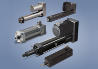
Electric linear actuators have come a long way, especially in the area of high force. Once upon a time when an application required high force, the usual linear motion solution was a hydraulic cylinder. However, as industrial automation gets more sophisticated and the need for precise control of speed, force and other variables grows, more engineers are considering electric high force linear actuators.
Now, it often happens that new high-force linear actuator applications go with electric actuators. Also, machine designers are converting existing linear motion systems from hydraulic to electric due to the technology’s many benefits. But converting from hydraulic to electric requires some thought, with a process that involves considering the actual force output of the cylinder, the duty cycle and the motion profile.
There are various ways to determine the actual force output of a hydraulic cylinder in an application. Since these components operate using pressurised oil inside the cylinder bore, you can use the basic formula:
Force = Area x Pressure
A simple calculation based on the cylinder’s bore and the rated system pressure will provide an estimate of the potential force output. However, this calculation may not give you the true story. The calculation will provide the force the cylinder could optimally deliver. Since it’s common practice to over-size cylinders, using this simple calculation will overstate the force required. It’s much more accurate to use the application’s actual values.
Let’s look at a real-life example: an application with a 3.5in (100mm) diameter cylinder with a 1.5in (45mm) diameter rod operating with a servo-hydraulic valve. During the cylinder’s extend stroke, the maximum pressure is 1,500 PSI (103 Bar). On the rod end of the cylinder, the down-side (or return line to the reservoir) pressure is 1,000 PSI (69 Bar). Here are two common ways that output force might be calculated:
OPTION 1 – System pressure and piston area only:
- Force = Area (πx r2) x Pressure
- Force = (πx 1.752) x 2,500
- Force = 9.62 x 2,500
- Force = 24,050 lbf (107 kN)
OPTION 2 – Work port pressure and piston area only:
- Force = Area (πx r2) x Pressure
- Force = (πx 1.752) x 1,500
- Force = 9.62 x 1,500
- Force = 14,430 lbf (64.2 kN)
The problem is that neither of these methods is very precise, and precision matters with electric linear actuators. While the cost of an oversized hydraulic cylinder may not hurt the budget, an oversized electric actuator will be expensive and harm the project’s return on investment. To get a precise calculation of output force, we recommend a method which looks at the difference between input and output force.
- Force = (A1 x P1) – (A2 x P2)
- A1 = Piston surface area
- A2 = Effective surface area of cylinder
- Area = πx r2
- P1 = Blind-end (piston side) pressure (PSI) or (Bar)
- P2 = Rod-end pressure (PSI) or (Bar)
Using this formula as a third option, we have:
- Force = (A1 x P1) – (A2 x P2)
- Force = [(πx 1.752) x 1,500]
- – {[(πx 1.752) – (πx 1.752)] x 1,000}
- Force = (9.62 x 1,500) – (7.85 x 1,000)
- Force = 14,430 – 7,850
- Force = 6,580 lbf (29.28 kN)
There’s a 70% difference between this result and that of Option 1. That translates into a major cost difference when considering an electric actuator. Imagine the potential for savings.
Converting a hydraulic high-force linear actuator to electric goes beyond determining force requirements. You need a fundamental understanding of the process to ensure that your final electric linear motion system is appropriately sized.
Start by defining the entire extend and retract cycle, including distances, speeds, duration of dwells, and even acceleration/deceleration times. Variables like speed and force may not be consistent throughout the entire motion profile. Often there are periods during which very high speeds or an increase in force is required. These portions of the motion profile need to be accounted for in addition to the remainder of the cycle.
Linear motion control components (actuators, servo motors, power screws) have peak and continuous ratings for speed and force and can only operate in the peak area of their ratings for brief periods of time throughout the process. During one complete motion cycle (extend, dwell, retract, dwell), the average speed and force must fall within the continuous operating region of the components’ ratings. Exceeding the continuous operating region of any of these components can diminish service life.
Hydraulic high-force linear actuator applications can have varying thrust requirements throughout their cycles. It is quite common, though, to have a consistent speed in one or both directions. This can make determining your cycle times easy. We recommend taking a video or using a stop watch to determine the duration of every move and dwell in the motion cycle.
If you’re putting in the effort to convert a hydraulic system to electric, look at the process itself for improvements. For example, a hydraulic application may cycle full stroke (extend and retract) during a repetitive pressing application. An electric actuator may need to extend and retract only 1in or 25mm to perform the same process, only performing a full retract for changing tooling or servicing. This can mean significant time savings.
Processes also may benefit from improvements through utilising the ability of a servo-controlled electric linear motion system to fully control position, velocity, acceleration/deceleration and force. These improvements can lead to increased part quality and reduced product scrap or rejects.
Once you’ve figured out your application’s forces and speeds, you can select the actuator power screw, servo motor and drive to complete the electric linear motion system. When making your selection, also consider the application’s requirements for size, weight, service life, IP rating and other factors.