Posted to News on 27th Mar 2017, 00:00
How to specify simple, reliable and adaptable screw jacks
The requirement to raise a load is often achieved with a screw jack, but these need to be used in conjunction with other drive components and possibly in a system of several synchronised screw jacks. Ian Carr of Drive Lines explains how lifting systems are typically designed.

Screw jacks provide linear motion, and so are used to lift, lower, position, align and hold loads. In this they are similar to hydraulic and pneumatic cylinders, their advantage being they don’t need an expensive power pack or compressor, just a simple motor drive system. Other attributes of screw jacks include that they are simple and therefore reliable, accurate in use, numbers of them can be synchronised to work together, and that their screw operation can be used to amplify force.
Essentially there are two types of screw jack: translating, in which the lifting spindle is driven axially through the gearbox, and rotating (or travelling nut), where the spindle is axially fixed and rotates to drive a travelling nut fixed to the load. The former is generally the more economic option, although with longer strokes the spindle may protrude through the bottom of the gearbox when retracted which can be a disadvantage. Unless fixed securely to the load, the spindle may rotate under friction when lifting, therefore an anti-rotation measure may be necessary. The latter, rotating type, ensures there is no protrusion below the gearbox, though the free end of the spindle will normally need securing by means of a flanged bearing.
Depending on the duty cycle or lifting speed required, a trapezoidal spindle or ball screw spindle can be selected. Trapezoidal spindles have the great advantages of being simple, robust, reliable, low cost and inherently self-locking. However, the greater expense of a ball screw can be justified. Because frictional losses are reduced significantly, they can operate at greater speeds and are highly efficient, so will require smaller motor drives. Ball screw jacks tend to be specified when frequent actuation is expected while trapezoidal screw jacks are favoured for systems that will be used less often. However as ball screws are not normally self-locking, a brake motor must be used in all cases to prevent back driving.
Selection of a screw jack for a given application may require some thought, in particular with calculating the optimum size – typically a unit that is big enough to cope with likely shock loads but not so big that it requires excessive power. Also, if travel speed is not important then, a smaller motor may be specified, saving cost.
Screw jacks are usually driven by a standard industrial AC motor, to which it is coupled by a shaft, couplings and gearheads, as appropriate. However, other types of motors could also be used, such as: DC in remote locations where an alternating current supply is unavailable; compact servo in space-limited applications; and air or hydraulic motors in potentially explosive atmospheres.
The configuration of the mechanical drive elements is often dictated by the physical layout of the system, and this element of the design project should be carefully scrutinised. Simplicity is always better than complexity because it aids efficiency and reliability. Engineers should also look for ways to design out possible failure modes: for instance an overhead system that pulls the load up is preferable to one that pushes from below because it is in tension rather than compression, therefore preventing buckling of the spindle if overloaded. For this reason smaller spindle sizes can often be used for expanding loads.
Beyond this, component selection is defined by power and efficiency requirements and may include right angled gearboxes, and line shafts of appropriate length. Engineers might also consider the duty cycle, working environment, etc, to specify the best components for a long, reliable and safe working life.
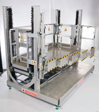
The simplest lifting systems will be designed around a single screw jack, but many loads will benefit from having multiple lifting points – typically four, one at each corner of a square or rectangular load. Six or even eight screw jacks may be used for long loads, while particularly large or irregularly shaped loads may have any number of screw jacks. In most cases a lifting system consisting of more than one screw jack will use a single motor, driving through the necessary configuration of line shafts and distribution gearboxes. This is the simplest and best way to ensure synchronicity of movement between the screw jacks. Alternative multi-motor designs would be possible, but they would have to be synchronised.
Another factor that must be considered is the guidance of the load, especially in compressive lifts. As already mentioned, the spindle buckling factor must be accounted for in our calculations; this factor is influenced by how rigidly the load is guided. It is important that screw jacks are not side loaded, as this can damage the spindle and bearings. Again, a smaller spindle may be possible if the load is very rigidly guided.


