


Posted to News on 1st Nov 2013, 00:00
Linear solutions for heavier loads
Screw jacks are the solution for achieving linear motion with medium to high forces at low to medium speeds. They are ready-engineered packages that are easy to use and they have multiple options so they can be readily customised to individual needs. Standard ranges cover forces from 5 to 1000kN (0.5 to 100 tonnes).
>Machine designers are attracted to the self-contained and easily controllable characteristics of screw jacks. Alternatives are ball screws, roller screws, hydraulic and pneumatic cylinders. To illustrate the adaptability of screw jacks, they are used in cranes, theatre lifts, steel rolling mills, radio telescopes, access doors, glass machinery and agricultural silos.
>Forces are generally above 1000N, and linear speeds can be anywhere from 0.1 to 300mm/s. Strokes can be up to 6m although short strokes around 100mm are common. Electric motors can be directly connected. Compared to hydraulic and pneumatic systems, electric driven screw jacks are preferred for their efficiency and ease of control.
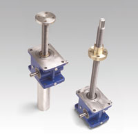
>Screw jacks are made with two design concepts: travelling screw and travelling nut. Both are based around a worm gearbox with cast housings in iron or aluminium. The worm input shaft in case-hardened steel meshes with a bronze wheel. With travelling screw designs, the bronze wheel has a second thread cut into its bore. Into this is located an acme screw shaft. When the bronze wheel is turned the result is linear motion with the screw passing through the housing. In the case of travelling nut designs, the acme screw is fixed to the bore of the worm wheel and rotates with it. A bronze nut mounted on the screw moves along it as the screw rotates. Choice between travelling screw and travelling nut depends on the mounting requirements.
>Screw jacks can be connected directly to an electric motor creating a compact linear drive. Standard 3-phase motors are most common. For lower powers DC motors can be used, or servo motors can achieve high performance.
>There are many variables to be taken into account when specifying a screw jack. The stroke can be up to 6m and is usually defined in 100mm increments. The orientation of the stroke can be in any direction and forces can be push, pull or both. Pull loads have the advantage that there is no tendency for the screw to buckle. Each size of jack will have three or four different ratios for the worm gear, and the linear speed range can be extended by choosing between threads with one, two or three starts. Increasing the number of starts increases the linear speed and the power required.
>Screw jacks selection is heavily influenced by the duty cycle, defined as the operating time over a 10 minute period. Heat generated in the worm gears limits the duty to around 30%, although this varies from model to model. The permissible duty can be increased by de-rating the force. Also high efficiency screw jacks with ball screws can be supplied capable of duties up to 100%.
>There are other performance limits that can come into play and advice may be needed from an experienced Engineer. Ambient temperatures above 25ºC require a de-rating. Bucking of the screw under push loads needs consideration and it depends on the way the load is guided. Starting torques may need to be checked because of the relatively low efficiency of the worm gears.
>Modular screw jacks with a wide range of options allow designers to specify a close-to-exact fit for individual needs. Thread wear can be monitored with safety nuts or with a wear-check modification. Screw jacks should not be driven to their mechanical limits and stroke limit switches can be supplied. Increased protection is available using bellows or a stainless steel screw.
>Multi-jack lifting systems use two, three or four jacks. For reasons of synchronisation, it is usual to employ a single geared motor, often with a double output shaft such as is possible with a helical bevel design. Connection between the screw jacks is made by spacer couplings and bevel gearboxes. Ideally the screw jack supplier will take responsibility for the specification and supply of the complete lifting system.