

Posted to News on 25th Feb 2014, 00:00
MicroTCA for industry
The latest updates to the MicroTCA specification extend its applications beyond research and into general industry, as the experts at Pentair-Schroff explain.
>There are many research institutes around the world whose activities are concerned with photons, elementary particles and astro-particle physics. These institutes build and operate complex physical systems such as particle accelerators, x-ray lasers and neutrino scales. Up to now, these experiments have frequently been controlled using VME systems. A few years ago, however, a group of staff from several research institutes began to look for a suitable platform for the next generation of their control systems. As a result they committed themselves to the xTCA standard.
>Although both MicroTCA and AdvancedTCA are well suited as platforms for these applications, both specifications lack certain important features. To implement these features, the xTCA base specification was created in 2009 within the PICMG working groups in order to extend the standard to include these extra functionalities. While in AdvancedTCA only additional signals in zone 3 were defined, it was necessary to adapt the MicroTCA specification to a greater extent; this was then realised in the sub-specification MTCA.4, 'Enhancements for Rear I/O and Precision Timing'.
>The researchers settled on xTCA for one principal reason: the carrier and shelf management, which both AdvancedTCA and MicroTCA specifications offer. Another factor is the redundancy that allows elements to be swapped while the system is in operation. The integrated carrier and shelf management makes it possible to monitor the status of all components in the system at any time and to respond to error statuses. It also allows the system to be remotely maintained; all operational statuses can be read and monitored from a remote control room. This is of particular importance for particle accelerators, for example, since no access is permitted to any part of the accelerator ring, where the control and monitoring systems are installed, while experiments are in progress.
>However, other features were also required that were not implemented in the MicroTCA base specification. For one thing, additional rear transition modules (RTMs) are necessary to accommodate the large number of I/Os on the rear front panels and to physically separate digital and analogue I/Os. Another factor is that the advanced physics community requires high-precision clock and trigger signals. The PICMG working group 'xTCA for Physics' was therefore set up, and this has now defined a suitable MicroTCA sub-specification known as MicroTCA.4. This specification is, however, also of interest to other market segments in industry (for example in testing and measurement), since the same requirements are often also found there. While the name of the working group was still 'xTCA for Advanced Physics', the specification was renamed 'Enhancements for Rear I/O and Precision Timing' in order to indicate its suitability for other applications as well. As an active member of this PICMG working group, Pentair provided support during development of the specification by producing the first Schroff systems.
>The rear I/O area and the board cage at the rear required specific further development. The idea was to feed in sensitive high-frequency analogue signals to the rear of the system in the rear I/O section, to process them there, convert them into digital signals and then to pass them forward to the processor units in the front board cage. Here the biggest challenge was realising the rear I/O board cage in connection with the MicroTCA direct connector. Extensive tolerance calculations were necessary to verify that front and rear connectors were securely inserted and that the MicroTCA connector contacted securely. Additionally, management for the rear transition modules and ventilation for the rear I/O area were defined.
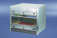
>The module size used in the front area was the double mid-size module (height 150mm, width 4 HP, depth 180mm). The mid-size width allows the maximum possible number of twelve AdvancedMC modules including two MCHs (MicroTCA carrier hubs) and up to four power modules to be fitted into one 19in wide system. For the modules on the rear, the rear transition modules, the same area was selected as for the front module. The MicroTCA.4 system is therefore about twice as deep as a MicroTCA.0 system.
>The front modules are connected directly to the rear modules via a connector and not via a backplane. This sounds simple but can lead to difficulties with regard to the length tolerances and the centring or fixing of the modules in the system. In a MicroTCA.0 system the front modules are centred through the connector positioned on the backplane and held in this position by the handle of the front panel. In the MicroTCA.4 system, this solution would cause the AdvancedMC module to move away from the centre position when the rear module is inserted, leading to possible discontinuities or short circuits in the MicroTCA connector.
>
Simple and effective solution
The designers have come up with a solution that is as simple as it is effective. Use is made of the special screw fitting of the AdvancedMC modules defined in the Rugged MicroTCA specification MTCA.1, which holds the AdvancedMC securely in its centred mounting position. Most important now, however, is the order in which the front and rear modules are fitted. First the front module is inserted and the front panel bolted into place. Next, its associated rear module is inserted from the rear and bolted tight. Thus both front and rear modules remain in their intended positions. Now either front or rear module can be removed or inserted without the need to observe any particular sequence.>For cost reasons and in order to make effective use of the existing Eco system, the rear module is designed in such a way that a front module is simply rotated through 180° and hinged backwards. Thus the locking mechanism is at the top (on front modules it is at the bottom). This also has the advantage that the insertion forces act at exactly the points where they are required. The rear I/O connector and its mating connector are both on top.
>A further significant addition over MTCA.0 was the expansion of the clock and trigger signals, originally conceived for telecommunications uses. MicroTCA.0 defines three telecommunications clocks. Revision 2.0 of the AdvancedMC specification increases this to four telecoms clocks and one fabric clock for PCI Express (PCIe). For measuring purposes, however, additional, extra high-precision clock and trigger signals are required. These topologies have now been realised in the previously undefined section of the pinouts of the AdvancedMC board.
>Extensions were also required in the area of management for MTCA.4. In MTCA.0, IPMB-L and IPMB-0 are already defined. IPMB-L links the MCMC (MicroTCA carrier management controller) of the MCH (MicroTCA carrier hub) with the MMCs (module management controllers) of the AdvancedMC modules in a radial architecture. IPMB-0 links the MCMC of the MCH with the EMMCs (enhanced module management controllers) of the PMs (power modules) and CU (cooling unit) in a bussed, redundant architecture. It was still necessary to link the new rear transition modules into the management. The working group also decided to tie each RTM via an I_C bus to its respective AdvancedMC module. Then the rear module is managed in the same way as the managed FRU (field replaceable unit) of the front module.
>MicroTCA.4 defines active cooling for the front and rear modules. The two areas can also be cooled independently of one another, which is made possible by placing active logic on the rear modules. With a fan management system more advanced than that of MicroTCA.0, the front and rear areas can be independently regulated via the MCH in a number of steps from zero to maximum fan speed.
>The MicroTCA.4 specification was ratified in August 2011 and since then several MicroTCA systems with rear I/O have been introduced to the market that match the specification as it currently stands. In the physics community it is already being used, for example, to control ring accelerators in high-energy physics.
>So, from a seemingly specialised application area, the trend now is a migration back to the industrial sector for certain applications that require the additional rear I/O, high availability, redundancy and remote maintenance features. MicroTCA.4 is now being considered and even adopted in the fields of industrial automation, image processing, real-time motion control, medicine, transportation and testing and measurement - a true sea change for the specification.
Unit 4, Grovelands Business Centre
Boundary Way
HP2 7TE
UNITED KINGDOM
+44 (0)1442 240471