

Posted to News on 25th May 2015, 00:00
Position sensors in safety applications
Mark Howard of Zettlex outlines design approaches that equipment designers should consider for position sensor arrangements to ensure safe and reliable equipment operation.
>Position sensors are a common element in modern control systems for a plethora of equipment. In some cases, if a position sensor fails there may be no implication for safety, whereas in other cases the potential consequences may be catastrophic. So let's look at the use of position sensors in safety applications.
>Firstly, we should define some terminology. For clarity and brevity, we will be using the term 'position sensor' to cover devices such as encoders, transducers and transmitters that measure angle, linear displacement, angular or linear speed and correspondingly output an electrical signal. Such devices can take a variety of formats such as potentiometers, Hall sensors, optical and inductive encoders.
>In particular, 'failure' needs to be considered carefully. Let's consider three types of failure:
>1. No output - the sensor stops reporting its output signal either permanently or intermittently
>2. Incorrect output with error flag - output from sensor is incorrect but this is flagged by the sensor
>3. Incorrect output with no error flag - sensor outputs an apparently correct reading but is actually reporting incorrect position.
>Other useful terms are 'safety relevant' and 'safety critical', and these terms are often mistakenly interchanged. 'Safety relevant' generally refers to an instance where position sensor failure may have some safety implications, whereas 'safety critical' generally means that failure has significant safety implications.
>When designing position sensor arrangements for safety related applications, it is useful to think in terms of a spectrum ranging from zero safety relevance to safety critical. As the degree of safety relevance increases, the most appropriate sensor arrangement changes. It is also worthy of note that as the safety relevance increases, generally the cost of the solution also increases. The optimal design approach applies the most appropriate sensor arrangement to the relevant safety requirements.
>As safety relevance increases, the first step in the engineer's armoury is to employ a sensor which can output an error flag instead of, or as well as, its output signal. Such error flags can take a variety of forms. For example, with an analogue sensor with a 0.5 to 10V output then the output can be reduced to <0.5V as an error signal. Similarly, devices such as modern inductive encoders (or 'incoders') with digital outputs like SSI or SPI, can be configured so their communication protocol carries an error flag if necessary.
>These error flags are triggered if one or more internal checks are not as they should be. Examples include internal watchdog timer, internal flash data memory check or a timeout for receipt of a clock signal. Such sensors can continue to operate but the output contains a caveat which tells the host system: "I'm giving you this data but watch out - it may be wrong". The receipt of such a flag by the host system should then be used to trigger going to a fail-safe state. A sensor which outputs its own error flag is said to be 'internally referenced'.
>As safety relevance increases further, sensors should be referenced externally and, in turn, both internally and externally. We can illustrate this with an example of a microwave communications antenna on a ship. Such antennas are typically required to move within a (software) defined arc so that on-board personnel are not affected by the microwave energy. The failure of a position sensor on one of the antenna's axes can potentially lead to unsafe conditions.
>Such antennas are typically driven in azimuth and elevation axes by electric motors driving through a gearbox. The angle of the gearbox output shaft is typically measured by an absolute angle encoder whose failure can be internally monitored by the sensor itself and referenced by an internally generated error flag. Additionally, the output from a resolver or encoder on the motor's shaft (input to the gearbox), can be counted by the host system and used as a rough guide to the approximate angle of the antenna axis. Should the two measurements differ outside of the expected bands then the microwave energy may be halted as the fail-safe condition.
>The next step along the safety spectrum is to use redundant or duplex arrangements whereby two sensors are used to measure the same parameter - such as the rotation angle of a shaft. The safety of such arrangements can be increased further by using different types of sensor so that their failure modes differ.
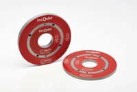
>An example of a duplex (electrically redundant) sensor is shown left in which the first sensor is shown on the inner ring and the second is shown on the outer ring. Whilst both sensors have a common mechanical housing, each operates electrically independently. Each has its own set of 10 built-in-tests and corresponding error flagging functionality.
>The inner and outer devices differ by virtue of different numbers of winding pitches on inner and outer rings, and their electronics may also be chosen to be very different. This further helps mitigate against common failure modes and is one of the reasons why such devices are increasingly chosen for demanding, hi-reliability applications. Higher safety demands might also require mechanical redundancy - for example using two sets of mechanical components, again preferably arranged such that their failure modes differ.
>A common adage in safety related system design is that when two sensors measure the same parameter, if one of the sensors gives an incorrect output it may not be obvious which one is wrong. Accordingly, the host system should be engineered such that it continues to operate only if the two sensors agree within reasonable bounds.
>Of course, whenever safety is a concern, it is an absolute must that highly robust and reliable sensors are selected. Nevertheless, no matter how reliable, every sensor has a finite mean-time between failure. It should also be the case that the host control system should be arranged so that, as far as practical, reasonableness tests can be employed. These tests may include for example:
>* Out of bounds measurements
>* Impossible steps in position or speed
>* Cross referenced motions
>* Out of bounds energy consumption.
>Notably, duplex arrangements are less reliable than simplex systems because of the inherently greater electrical and mechanical complexity. The most demanding applications - in aerospace, military and oil and gas applications - might also require that the host system continues to operate in the case of sensor failure. In such instances it may be the case that a triplex arrangement is required whereby the host system is configured so that a voting arrangement can be instigated. In other words, at least two of the three sensors must agree within reasonable bounds for the equipment to operate. At an extreme, all three sensors should differ such that all three do not have common failure modes and, as far as practical, the system should include some elements of mechanical redundancy.