Posted to News on 22nd Jan 2016, 00:00
Understanding electromagnetic clutches and brakes
In this article the experts at Techdrives guide us through the intricacies of electromagnetic clutches and brakes.

Electromagnetic clutches and brakes are old technology that has changed little in the past 20 years. Decentralised drives have reduced their use but varied cases remain where the ability to connect, disconnect, stop and hold is irreplaceable. Electromagnetic clutches and brakes have largely become standardised in Europe with near-interchangeable dimensions. Torques are typically in the range 3 to 500Nm although there are niche exceptions, even up to 2000Nm or more. Typical shaft sizes are 5 to 80mm.
Clutches are used to connect and disconnect parts of a machine without having to stop and start the motor. Brakes suit dynamic stopping duty and/or holding. A typical European range is offered by Intorq, whose range covers 7.5 to 480Nm in seven sizes with outside diameters from 63 to 250mm. All models use the same concept of generating magnetic flux by applying DC voltage to a coil. The magnetic flux pulls in a steel plate onto a surface with embedded friction material.
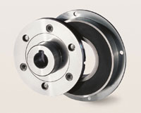
There are two parts to an electromagnetic brake. Firstly the coil part known as the stator is mounted to the machine frame. The coil is wound to fit inside the stator and a ring of friction material sits above it, glued into place. The steel stator in cross section can be considered as the ‘U’ shape of a horseshoe magnet and the energised coil focusses the magnetic flux at the rings of the inner and outer surfaces. These are known as the poles (hence these clutches and brakes are sometimes known as
pole face).
The second part is the armature assembly consisting of a steel armature plate connected through a flat pre-stressed spring to an aluminium hub which is in turn connected to the shaft. When the armature plate is mounted close to the stator, the magnetic flux in the poles can attract the armature across the air gap, generating torque from friction between the two surfaces in contact.
The friction surface of the stator is flat, that is the
inner and outer steel poles are flush with the ring of friction material. This can look like the brake is worn out but in fact a flat surface is needed so that the magnetic flux path can be closed for maximum attractive force. The steel and the friction material wear down together in service.
One clever design feature is the pre-stressed spring with a connection riveted alternately between the armature plate and the flanged hub. This is well suited to the relatively small axial movement and allows backlash free torque transmission. Being pre-stressed, it also gives free release when the power is removed.
Clutches use the same concept to connect two rotating shafts. To avoid using brushgear, the stator is now split into two parts – the clutch stator with the coil and the clutch rotor with the friction material. They mount closely together but without the rotor touching the stationary stator. Magnetic flux crosses radially between them and a small increase in coil power compensates for the extra resistance. Easier to use and therefore recommended for general applications are clutches where the rotor is bearing mounted onto the stator. This becomes a two-piece clutch with a stator/rotor and an armature. A lug with a loose fitting pin prevents the stator from rotating.
Electromagnetic clutches and brakes are funda-mentally fixed torque devices. Varying the applied voltage to control torque is not effective as the coil resistance changes with temperature. Varying the current to control torque is possible but difficult due to hysteresis effects. However a well-designed clutch or brake will deliver a consistent rated torque without much difference between static holding and dynamic operation at 100r/min. Higher slip speeds lead to a reduction in transmitted torque but it is unusual for the loss to be more than 20-30%. For stable torque levels it is essential to keep the friction surfaces free from water, oil and grease. The friction material is a mix of organic fillers on resins which absorb contaminants like a sponge. Making them clean again is nearly impossible.
There are four different armature designs available to suit different mountings. Type 1 connects to a shaft. A brake variant is type 2 where the hub is reversed making a compact assembly. Type 3 omits the aluminium flanged hub leaving only the armature plate and spring – a lower cost option that can be incorporated into the machine design. Finally armature type 5 is a clutch armature complete with bearing support for offset drives.
The vast majority of electromagnetic clutches and brakes use low voltage DC coils, mostly 24V but 12, 36 and 48V are possible. Low power requirements lead to typical current of 10 to 85W. As the coils are inductive, response times are finite. For example a 30Nm brake might take 60ms to engage and 30ms to release. Where this is not satisfactory there are ways to reduce the engagement time by up to 90% through over-excitation. Release times are more difficult to reduce but if a lower holding voltage can be used the times will fall. Sparking at the switch terminals on switch-off is another result of the inductivity and suppliers can recommend suppressors to suit frequent switching.
Sizing of clutches and brakes is usually based on the required torque multiplied by a service factor of twp or more. Where there are significant inertias and repeated dynamic engagement, the maximum operating frequency should be checked from catalogue data.
Clutch and brake mounting is an area that often leads to confusion. However, there are some simple rules:
- Concentricity is important, observe catalogue values
- Choose clutches with a one piece stator/rotor whenever possible
- Use offset drives instead of in-line to reduce shaft alignment work
- Include parts for axial fixing and accurate setting of the air gap.
- Where there is frequent dynamic engagement, make provision for adjustment of the airgap after wear.
When a brake using an armature type 3 is connected to a pulley., the stator is centred to the shaft using the lip of a bearing. The air gap between the stator and armature is set by a spacer and shims, clamped in placed by a bolt and cap at the end of the shaft.
Shaft to shaft in-line clutch connections are difficult to achieve. Required concentricity can be as low as 0.2mm. Even then, setting of the axial positions to achieve the required air gap – typically 0.3 ±0.05mm – is intricate and time consuming with shims, circlips and an end cap. A better solution is an offset drive or, when in-line is essential, suppliers may be able to offer a clutch/coupling.
Offset drives with a V-belt pulley, timing belts and gears are possible. Here an armature type 5 with bearings supports the customer’s pulley. An alternative is to use the type 3 armature and to combine the bearings with pulley. The one piece stator/rotor is mounted outboard so that the side loads from the belt are closer to the support bearings. The use of disc springs between the rotor and the first bearing which allows the air gap to be easily adjusted using the end cap and bolt.
Electromagnetic clutches and brakes are a mature technology but with widespread applications for example in packaging machinery, materials handling, office and printing equipment, gates and doors. They can be highly reliable witnessed by typical B10 values (lifetime to 10% failure) of 3 million operations. In the UK the Intorq product range is sold and technically supported by Techdrives.


